


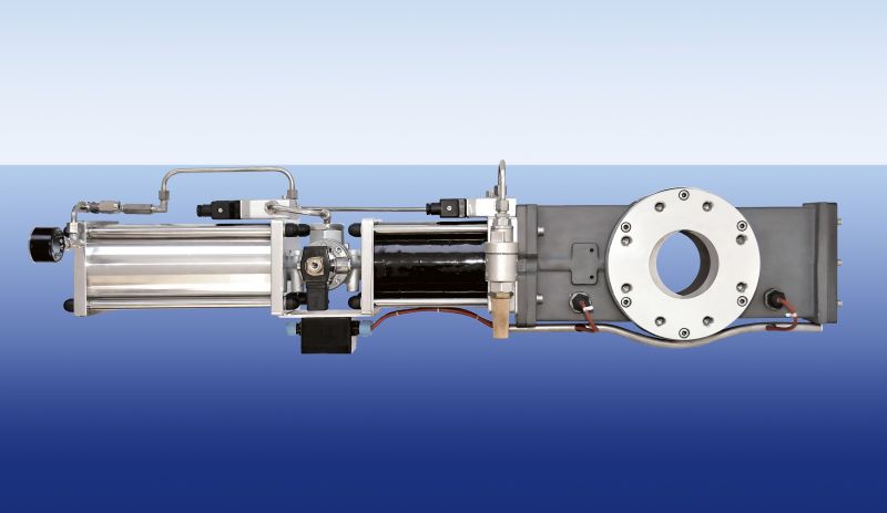
Quick-closing valves (decoupling)
Technical specifications
| Protection class | |
| Connection: | Flange pursuant to DIN EN 1092-1 Form A, drilled according to PN10 or ASA 150 lbs. (further such as JIS on request) |
| Temperature: | -10°C up to 100°C |
| Compressive strength: | Flame-propagation-proof and pressure-shock-proof up to 10 bar (certified pursuant to ATEX) |
| Propulsion medium: | Compressed air from the factory compressed air supply with an operating pressure of 6 bar |
| Closing times: | < 50 msec |
| Housing material: | Silumin, stainless steel |
| Options | Sealing over double O-ring system, liner or else pipe use in 1.4571 |
The quick-closing valve is a component for a system of protection.
In the event of an incident, the gate closes within milliseconds, thereby avoiding possible secondary explosions.
The Kammerer-quick-closing valve is used in various industries, e.g. chemicals, pharmaceuticals, energy, food industry, automotive industry, wood industry, R&D etc.
In the case of interest, we look forward to your inquiry.
Download material can be found here.
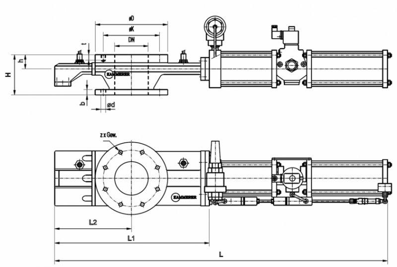
| DN (mm) | Building length (mm) | Building height (mm) | Flange (mm) |
Flange thickness (mm) |
Connection dimensions (drilled acc. to PN10) |
Determined closing time in ms (deviations of +/- 0.2 to 2 are possible.) |
Weight in kg for silumin |
|||||
|---|---|---|---|---|---|---|---|---|---|---|---|---|
| L | L1 | L2 | H | h | ø D | b | ø d | Z x Gew | ø K | |||
| 50 | 734 | 327 | 147 | 120 | 53 | 165 | 18 | 18 | 4xM16 | 125 | 23,4 | 22 |
| 65 | 806 | 364 | 174 | 120 | 53 | 185 | 18 | 18 | 4xM16 | 145 | 23,4 | 24 |
| 80 | 945 | 437 | 223 | 120 | 53 | 200 | 16 | 18 | 8xM16 | 160 | 24 | 26 |
| 100 | 1123 | 472 | 230 | 120 | 53 | 220 | 17 | 18 | 8xM16 | 180 | 24,8 | 30 |
| 125 | 1240 | 576 | 286 | 150 | 53 | 270 | 20 | 18 | 8xM16 | 210 | 40,1 | 35 |
| 150 | 1365 | 626 | 307 | 120 | 53 | 285 | 19 | 22 | 8xM20 | 240 | 27,7 | 38 |
| 200 | 1640 | 791 | 384 | 150 | 58 | 340 | 21 | 22 | 8xM20 | 295 | 35,1 | 50 |
| Diameter (inch) | Building length (inch) | Building height (inch) | Flange (inch) |
Flange thickness (inch) |
Connection dimensions (drilled acc. to ASA 150 lbs.) |
Determined closing time in ms (deviations of +/- 0.2 to 2 |
Weight in lbs for silumin |
|||||
|---|---|---|---|---|---|---|---|---|---|---|---|---|
| L | L1 | L2 | H | h | ø D | b | ø d (inch) | Z x thread (inch) / [UNC] |
ø K (inch) | |||
| 2 | 29 | 13 | 6 | 5 | 2.1 | 6.5 | 0.71 | 0.71 | 4 ⅝“ | 4 | 23.4 | 48.50 |
| 2.5 | 32 | 14 | 7 | 5 | 2.1 | 7.3 | 0.71 | 0.71 | 4 ⅝“ | 5 | 23.4 | 52.91 |
| 3 | 37 | 17 | 8 | 5 | 2.1 | 7.9 | 0.62 | 0.71 | 4 ⅝“ | 6 | 24 | 57.32 |
| 4 | 44 | 19 | 9 | 5 | 2.1 | 8.7 | 0.67 | 0.71 | 8 ¾“ | 7 | 24.8 | 66.14 |
| 5 | 49 | 23 | 11 | 6 | 2.1 | 10.6 | 0.79 | 0.71 | 8 ¾“ | 8 | 40.1 | 74.96 |
| 6 | 54 | 25 | 12 | 5 | 2.1 | 11.2 | 0.75 | 0.87 | 8 ¾“ | 9 | 27.7 | 83.78 |
| 8 | 65 | 31 | 15 | 6 | 2.3 | 13.4 | 0.82 | 0.87 | 8 ¾“ | 11 | 35.1 | 110.23 |
As of DN 400 on request against individual certificate.